What Is a Breadboard? The Secret Holes That Make Circuits Easy! 🔌
I kept pushing wires into a breadboard and nothing worked — until I learned what's actually INSIDE it! Anatomy, power rails, first circuit, and the mistakes I made so you don't have to.
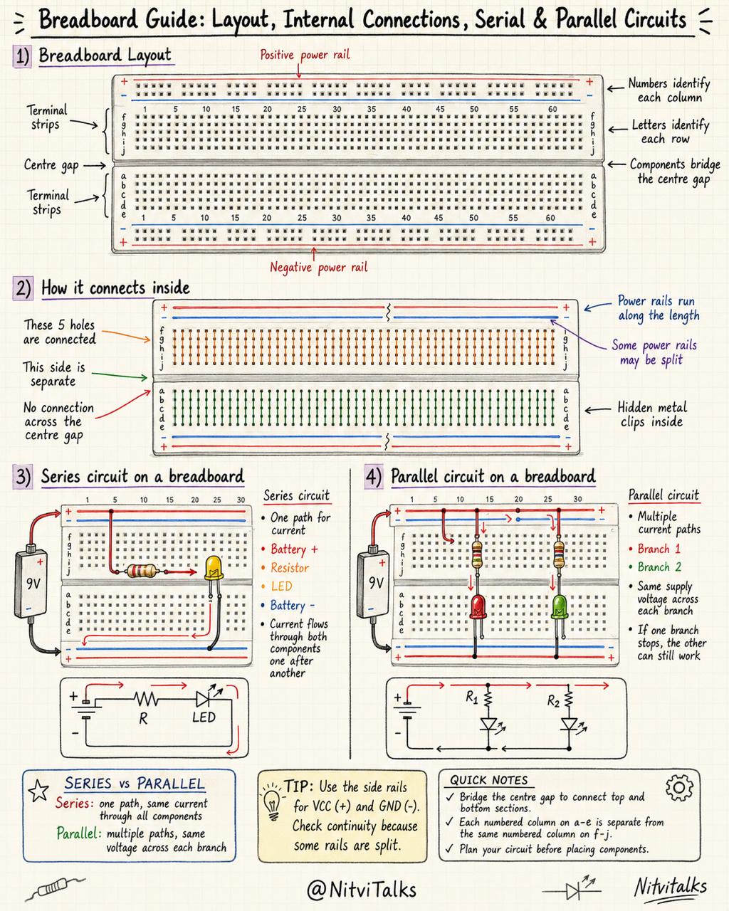
When I first saw a breadboard, I thought it was just a plastic board with holes. I pushed wires in randomly… and nothing worked. 🤷♀️
Then I learned the secret — there are metal clips hidden inside connecting the holes in a special pattern! Once I saw that, everything made sense.
Let me show you what's inside a breadboard, how the holes connect, and how to build your very first circuit — no soldering needed! 🚀
🧩 What Is a Breadboard, Really?
A breadboard is a solderless circuit board — you push components and wires into the holes, and the breadboard connects them for you. No melting, no soldering iron, no waiting. You can build, test, and rebuild circuits in seconds!
"A breadboard is like a LEGO baseplate for electronics. You just push things in, and they connect. No solder, no glue, no mess — and you can reuse it forever!"
🔍 The Secret Inside: How the Holes Connect
This is the part that blew my mind 🤯. The holes on top look the same, but underneath, metal clips connect groups of holes together. If you know which holes are connected, you can build any circuit!
Power Rails (the long rows top & bottom)
On the edges of the breadboard, you'll see red and blue lines next to long rows of holes. These are the power rails.
- Red row (+) → connect to positive (e.g. 5V from Arduino or battery +)
- Blue row (−) → connect to negative / GND
- All holes in the same row are connected left-to-right
- There's a gap in the middle — the left half and right half are NOT connected!
Tie Points (the short rows in the middle)
In the middle of the breadboard, holes are grouped in rows of 5, split by a wide gap down the centre. Each row of 5 is one tie point — all 5 holes are connected inside.
- Each column of 5 holes = one connection point
- Different rows are NOT connected (until you add a wire)
- The centre gap separates the top half from the bottom half — this is so you can plug in a chip (IC) across the gap
   + ─ ─ ─ ─ ─ ─ ─ ─ ─ ─ ─ ─ ─ ─ ─ ─ ─ +   ← RED power rail (+)
   │ . . . . . . . . . . . . . . . . . │
   │ . . . . . . . . . . . . . . . . . │   ← BLUE power rail (−)
   ─ ─ ─ ─ ─ ─ ─ ─ ─ ─ ─ ─ ─ ─ ─ ─ ─ ─ ─
   . . . . │ . . . . . . . . │ . . . . .   ← tie points (rows of 5)
   . . . . │ . . . . . . . . │ . . . . .      Each row = 1 connection
   . . . . │ . . . . . . . . │ . . . . .
   . . . . │ . . . . . . . . │ . . . . .
   ═══════════════════════════════════════   ← centre gap (for ICs)
   . . . . │ . . . . . . . . │ . . . . .
   . . . . │ . . . . . . . . │ . . . . .
   . . . . │ . . . . . . . . │ . . . . .
   . . . . │ . . . . . . . . │ . . . . .
   ─ ─ ─ ─ ─ ─ ─ ─ ─ ─ ─ ─ ─ ─ ─ ─ ─ ─
   │ . . . . . . . . . . . . . . . . . │   ← BLUE power rail (−)
   │ . . . . . . . . . . . . . . . . . │
   + ─ ─ ─ ─ ─ ─ ─ ─ ─ ─ ─ ─ ─ ─ ─ ─ ─ +   ← RED power rail (+)
"Look closely — see those red and blue lines? Those are the power rails, they carry electricity across. And these little groups of 5 holes in the middle? Each group is one connection. The gap in the centre is for plugging in chips!"
🤯 The Aha Moment — There Are Metal Clips Inside!
Here's the secret that made everything click for me. Underneath each row of 5 holes, there's a tiny metal clip that grabs the wire and connects it to the other 4 holes in that row.
So when you push a wire into hole A and an LED leg into hole B in the same row — they're connected automatically! No wire needed between them.
"This is the part that blew my mind — there are tiny metal clips hiding inside the breadboard! Each row of 5 holes has one clip that connects them all. So you don't even need a wire between two things in the same row!"
💡 Let's Build a Circuit: LED + Resistor + Battery
LED short leg (−) → a different row (e.g. row 6)
"Watch this — I plug the battery into the rails, drop in a resistor, then the LED, and… it lights up! See how the breadboard does all the wiring for me? I didn't have to solder a single thing."
⚠️ Mistakes I Made So You Don't Have To
"I made all these mistakes! The one that got me was putting both LED legs in the same row — I thought the breadboard was broken. Turns out the legs were connected to each other! Remember: different rows for each leg."
✨ Nitvi's Pro Tips
- Colour-code your wires: Red for +, black/blue for −, yellow/green for signals. It makes debugging 10× easier!
- Trim resistor legs slightly so they sit flat — long wobbly legs can touch each other and short your circuit.
- Always power off the battery or unplug USB before changing wires. I learned this after a tiny spark! ⚡
- Use the centre gap for chips: If you ever add an IC (like a 555 timer), straddle it across the gap so each pin gets its own row.
- Draw your circuit first on paper. It's way faster than pulling wires in and out!
🎮 Try It Yourself: Series vs Parallel
Now you know how a breadboard works — but how do you wire multiple LEDs? There are two ways: series (one after another in a loop) and parallel (each LED gets its own path). They behave VERY differently! Switch modes, drag the sliders, and break a wire to see what happens. 👇
"This is my favourite simulator! Try breaking LED 1 in series mode — both LEDs go dark. Now switch to parallel and break LED 1 again — LED 2 stays on! That's why our homes are wired in parallel."
🚀 What's Next?
Now that you know how a breadboard works, you can build any circuit without soldering! In my next video, I'll add a push button so we can turn the LED on and off — and then we'll connect it to an Arduino!
👉 Just played with the Series vs Parallel sim above? Try the others on the simulations page!
👉 Watch my first LED project if you missed it.
👉 Learn Ohm's Law to pick the perfect resistor every time.
If you're learning Arduino, electronics, robotics, or STEM just like me, join me on this exciting journey! 👍 Like, 💬 Comment, 🔔 Subscribe on Nitvi Talks on YouTube 💙
If you’re learning Arduino, electronics, robotics, or STEM just like me, join me on this exciting journey. 👍 Like, 💬 Comment, 🔔 Subscribe on Nitvi Talks!